Understanding Pulse Width Modulation (PWM) in Timer of STM32F407
- Encode AND Decode

- Sep 1, 2024
- 11 min read
What is PWM?
PWM is a method of controlling the amount of power delivered to an electrical load by varying the width of the pulses in a repetitive on-off signal. The signal remains digital (either fully on or fully off), but by changing the proportion of time the signal is high (on) versus low (off) within a given period, we can effectively control the average voltage delivered to a load.
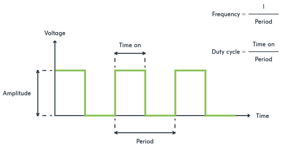
Duty Cycle: The duty cycle is how much of the time the signal is "on" compared to how much it is "off" in one cycle. For example, a 50% duty cycle means the signal is on for half the time and off for the other half, so the average voltage is half of the maximum.
Duty Cycle (%) = ( (ON Time) / (ON Time + OFF Time) ) × 100

Duty Cycle (%) = ( (ON Time) / (Total Period) ) × 100

Since Total Period = ON Time + OFF Time

On Time is the duration when the signal is high (ON).

Total Period is the total time for one complete cycle, including both the on and off times.
For example, if the signal is on for 2 milliseconds and the total period is 10 milliseconds, the duty cycle would be:
Duty Cycle (%) = ( 2ms / 10ms ) × 100 = 20%
Frequency: The frequency refers to how often the PWM signal completes one full cycle of being high (on) and low (off) per second. It is measured in Hertz (Hz).
The frequency is determined by the period of the PWM signal, which is the total duration of one complete cycle. The formula to calculate the frequency is:
Frequency (f) = 1 / Period(T)Where:
Period (T) is the duration of one complete cycle, including both the on and off times.
For instance, if the period of the PWM signal is 1 millisecond (ms), then the frequency would be:
Frequency (f) = 1/1ms = 1000Hz (or 1kHz)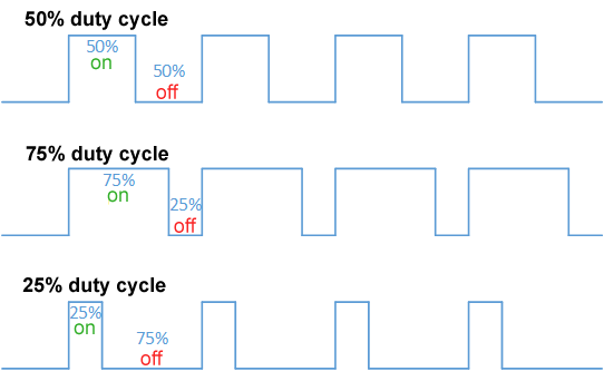
Use Cases of PWM signals
Motor Speed Control: PWM is widely used in motor speed control by varying the duty cycle of the PWM signal to adjust the average voltage applied to the motor. This, in turn, changes the motor's speed; a higher duty cycle means more power and a faster motor speed, while a lower duty cycle results in a slower speed.
LED Brightness Control: For LED brightness control, PWM is employed to adjust the average current flowing through the LED. By changing the duty cycle of the PWM signal, you can make the LED brighter or dimmer. A higher duty cycle increases brightness, whereas a lower duty cycle reduces it.
Servo Motor Control: In servo motor control, PWM signals are used to determine the position of the servo motor. The width of the pulse in the PWM signal corresponds to the angle of the servo. For example, a pulse width of 1.5 milliseconds might represent the center position of the servo, while widths of 1 millisecond and 2 milliseconds indicate the extreme positions.
Audio Synthesis: In audio synthesis, PWM can be used to create sound waves. By modulating the pulse width, you can generate various tones and sounds with different frequencies and amplitudes. Adjusting the PWM frequency and duty cycle allows for the synthesis of different audio signals.
Configuring PWM Using Timer 4 in STM32F407
We will be using general purpose Timer 4 to implement the PWM signal.
Timer 4 has a 16-bit counter, which means it can count from 0 to 65,535. This 16-bit range allows it to handle a variety of timing and PWM applications.
PWM Modes Supported by Timer 4
Timer 4 in the STM32F407 supports several PWM modes:
Edge-Aligned PWM (Mode 1: Active High, Mode 2: Active Low)
Center-Aligned PWM (Mode 3: Center-Aligned Mode 1, Mode 4: Center-Aligned Mode 2)
Complementary PWM Modes
One-Pulse Mode
Repetition Counter Mode
Synchronization with other timers
In this tutorial, we will focus on Edge-Aligned PWM.
Edge-Aligned PWM
Edge-Aligned PWM modes are widely used to generate Pulse Width Modulation (PWM) signals, controlling the signal based on the timer counter value relative to the Compare Register (CCR).
Auto-Reload Register (ARR):
Purpose: Sets the period of the PWM signal. The ARR determines how long the timer counts before resetting to zero.
Period Calculation: The period of the PWM signal is given by:
PWM Period = ( (ARR + 1) / Timer Clock Frequency) )How It Works: The timer counts from 0 up to the ARR value. Once the counter reaches ARR, it resets to zero and starts counting again, creating a repeating PWM cycle.
Compare Register (CCR):
Purpose: Determines the duration for which the PWM signal remains high within each period.
Duty Cycle Calculation: The duty cycle is given by: Duty Cycle:
Duty Cycle = (CCR / ARR+1) × 100%How It Works: The CCR value specifies the point in the timer period where the PWM signal transitions from high to low (or vice versa).
Edge-Aligned PWM Modes
Timer 4 supports two Edge-Aligned PWM modes:
Edge-Aligned PWM mode 1
Edge-Aligned PWM mode 2
Edge-Aligned PWM Mode 1 (Active High)
In this mode(counter is up counting), the PWM signal is high when the timer’s counter value is less than the Compare Register (CCR) value.
For example, if CCR is set to 999, the PWM signal will be high from the timer count of 0 up to 998.
As soon as the counter reaches the CCR value, the PWM signal switches to low. It stays low until the counter reaches the Auto-Reload Register (ARR) value.
Once the counter reaches ARR, it resets to 0. At this point, the PWM signal starts the high-low cycle again. The pin is high from 0 up to CCR, then goes low from CCR to ARR.
This cycle repeats continuously, creating a PWM waveform.
Example Calculation:
The PWM signal is high from the start of the period (0) to the CCR value. For instance, if CCR is set to 999, the signal is high from count 0 to 999.
The signal then goes low when the counter reaches CCR and remains low until it reaches ARR. If ARR is set to 1999, the signal stays low from count 1000 to 1999.
ARR = 1999: This defines the total period of the PWM cycle.
CCR = 999: This specifies the point at which the signal switches from high to low.
High Time: 1000 counts (from 0 to 999)
Low Time: 1000 counts (from 1000 to 1999)
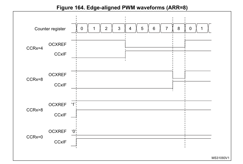
In the above diagram, the counter register (TIMx_CNT) starts counting from 0 when the timer is turned on. The CCRx register is loaded with the value 4, and the ARR register is loaded with the value 8.
In Edge-aligned PWM Mode 1 (Active High), the PWM output (controlled by the OCXREF signal) is initially high. The OCXREF (Output Compare Reference signal) signal is responsible for controlling the output pin.
When the counter finishes the 3 (as the counting starts from 0, this is the 4th count), it matches the value in the CCRx register, causing the output (OCXREF) to go low.
The output stays low until the counter reaches the value 8, at which point the timer overflows, resets to 0, and the output goes high again. This cycle then repeats.
Similarly, the diagram shows how the output behaves for different CCRx values.
In down-counting, channelx is inactive as long as CNT> CCRx, otherwise it is active.
Edge-Aligned PWM Mode 2 (Active Low)
In this mode (counter is upcounting), the PWM signal is low when the timer’s counter value is less than the Compare Register (CCR) value.
For example, if CCR is set to 999, the PWM signal will be low from the timer count of 0 up to 998.
As soon as the counter reaches the CCR value, the PWM signal switches to high. It remains high until the counter reaches the Auto-Reload Register (ARR) value.
Once the counter reaches ARR, it resets to 0. At this point, the PWM signal starts the low-high cycle again. The pin is low from 0 up to CCR, then goes high from CCR to ARR.
This cycle repeats continuously, creating a PWM waveform.
Example Calculation:
The PWM signal is low from the start of the period (0) to the CCR value. For instance, if CCR is set to 999, the signal is low from count 0 to 999.
The signal then goes high when the counter reaches CCR and remains high until it reaches ARR. If ARR is set to 1999, the signal stays high from count 1000 to 1999.
ARR = 1999: This defines the total period of the PWM cycle.
CCR = 999: This specifies the point at which the signal switches from low to high.
Low Time: 1000 counts (from 0 to 999)
High Time: 1000 counts (from 1000 to 1999)
In down-counting, channelx is active as long as CNT > CCRx, otherwise it is inactive.
Overview of Steps to Configure PWM Using Timer 4
In this tutorial, we will configure Timer 4 to generate a PWM signal in Edge-Aligned Mode 1 (Active High) with counter set to up counting to toggle the PD12 pin. The PWM signal will be generated using Timer 4 in up-counting mode, ensuring that PD12 will toggle according to the PWM signal.
Configure the Output Pin
First, you need to select the output mode by setting the CCS (Capture/Compare Selection) bits in the CCMRx register.
This configuration is necessary to define the pin as an output for PWM generation.
Following this, the polarity of the PWM signal must be determined. This is done by setting the CCxP (Capture/Compare x Output Polarity) bit in the CCER register.
The polarity setting controls whether the PWM signal will be active high or active low, allowing you to decide the initial state of the signal.
Select the PWM Mode
Next, select the PWM mode by setting the OCxM (Output Compare x Mode) bits in the CCMRx register. You can choose between PWM Mode 1 and PWM Mode 2.
In PWM Mode 1, the output signal remains high when the counter value is less than the compare value and goes low when it is equal to or greater than the compare value.
In contrast, PWM Mode 2 keeps the output low when the counter value is less than the compare value and switches it to high when the compare value is reached or exceeded.
Program the Period and Duty Cycle
The period and duty cycle are programmed by setting the period in the ARR (Auto-Reload Register) and the duty cycle in the CCRx (Capture/Compare Register).
The ARR value defines the complete duration of one PWM cycle, determining how long the timer counts before resetting.
The CCRx value controls how long the PWM signal stays in its active state (either high or low) within each cycle, thereby setting the duty cycle.
Set the Preload Bit
To ensure stable PWM output, enable the preload feature by setting the preload bit in the CCMRx register and the ARPE (Auto-Reload Preload Enable) bit in the CR1 register.
The preload ensures that changes to the period or duty cycle take effect only after an update event, preventing any sudden or unintended changes in the PWM signal.
Select the Counting Mode
If you're using PWM edge-aligned mode, configure the counter to count up or down.
In edge-aligned mode, the counter counts in one direction, and the output signal changes state at specified points during the count.
For PWM center-aligned mode, set the counter to operate in center-aligned mode by configuring the CMS (Center-Aligned Mode Selection) bits to a non-zero value.
In center-aligned mode, the counter counts up to the ARR value and then down to zero, creating a symmetrical waveform.
Enable the Capture/Compare Channel
After configuring the counting mode, enable the capture/compare channel by setting the corresponding enable bit in the CCER register.
This step activates the output compare function, allowing the timer to control the output pin based on your PWM settings.
Enable the Counter
Finally, start the PWM generation by enabling the counter in the CR1 register. Once the counter is enabled, the timer begins counting, and the output pin toggles according to the configured PWM signal, generating the desired waveform based on the period, duty cycle, and mode you’ve selected.
Source Code
#include "stm32f4xx.h"  // Include the STM32F4xx peripheral library header file

#define PERIOD  500  // Define the PWM period
#define DUTY    25   // Define the PWM duty cycle

// Function prototypes
void GPIO_Init(void);     // Function to initialize GPIO settings
void Timer4_Init(void);   // Function to initialize Timer 4 settings
void TIM4_IRQHandler(void); // Function for Timer 4 interrupt handler (not used in this code)

// Main function
int main(void) {
    GPIO_Init();   // Initialize GPIOD for PD12
    Timer4_Init(); // Initialize Timer 4 for PWM generation

    while (1) {
        // Main loop is empty; Timer 4 handles PWM generation automatically
    }
}

// GPIO Initialization for PD12
void GPIO_Init(void) {
    // Enable clock for GPIOD
    RCC->AHB1ENR |= RCC_AHB1ENR_GPIODEN;

    // Configure PD12 as an alternate function
    GPIOD->MODER &= ~GPIO_MODER_MODE12;        // Clear the mode bits for PD12
    GPIOD->MODER |= GPIO_MODER_MODE12_1;       // Set PD12 to Alternate Function mode

    // Set PD12 to AF2 (Alternate Function 2) for TIM4
    GPIOD->AFR[1] |= GPIO_AFRH_AFSEL12_1;
}

// Timer 4 Initialization
void Timer4_Init(void) {
    // Enable clock for Timer 4
    RCC->APB1ENR |= RCC_APB1ENR_TIM4EN;

    // Configure Timer 4 in PWM mode 1
    TIM4->CCMR1 |= TIM_CCMR1_OC1M_2 | TIM_CCMR1_OC1M_1;  // Set PWM mode 1 (Active High) for Channel 1

    // Select Output Compare mode for Channel 1
    TIM4->CCMR1 &= ~TIM_CCMR1_CC1S;   // Clear CC1S bits to use output compare mode

    // Enable preload register for Channel 1
    TIM4->CCMR1 |= TIM_CCMR1_OC1PE;

    // Enable auto-reload preload
    TIM4->CR1 |= TIM_CR1_ARPE;

    // Generate an update event to reload the preloaded values
    TIM4->EGR |= TIM_EGR_UG;

    // Set output polarity to active high
    TIM4->CCER &= ~TIM_CCER_CC1P;

    // Set prescaler to divide timer clock by 16000
    TIM4->PSC = 16000 - 1;

    // Set the auto-reload register (ARR) for the PWM period
    TIM4->ARR = PERIOD;

    // Set the compare register (CCR1) for the PWM duty cycle
    TIM4->CCR1 = DUTY;

    // Enable the output compare function for Channel 1
    TIM4->CCER |= TIM_CCER_CC1E;

    // Start Timer 4
    TIM4->CR1 |= TIM_CR1_CEN;
}
Source Code Explanation
int main(void) {
    GPIO_Init();
    Timer4_Init();
    while (1) {
       // The main loop can remain empty, everything is handled by the ISR
   }
}GPIO_Init();: Initializes GPIO pin PD12 to be used for the PWM output.
Timer4_Init();: Configures Timer 4 to generate the PWM signal.
while (1) { ... }: An infinite loop. Since Timer 4 handles PWM generation automatically, the loop remains empty.
void GPIO_Init(void) {
    RCC->AHB1ENR |= RCC_AHB1ENR_GPIODEN;
    GPIOD->MODER &= ~GPIO_MODER_MODE12;
    GPIOD->MODER |= GPIO_MODER_MODE12_1;
    GPIOD->AFR[1] |= GPIO_AFRH_AFSEL12_1;
}
RCC->AHB1ENR |= RCC_AHB1ENR_GPIODEN;: Enables the clock for the GPIOD peripheral. This is necessary to configure and use PD12.
GPIOD->MODER &= ~GPIO_MODER_MODE12;: Clears the mode bits for PD12 to reset its configuration.
GPIOD->MODER |= GPIO_MODER_MODE12_1;: Sets PD12 to Alternate Function mode. This allows PD12 to be controlled by Timer 4.
GPIOD->AFR[1] |= GPIO_AFRH_AFSEL12_1;: Configures PD12 to use Alternate Function 2 (AF2) for Timer 4 output. PD12 is set to the correct alternate function to output PWM signals.
void Timer4_Init(void) {
    RCC->APB1ENR |= RCC_APB1ENR_TIM4EN;
    TIM4->CCMR1 |= TIM_CCMR1_OC1M_2 | TIM_CCMR1_OC1M_1;
    TIM4->CCMR1 &= ~TIM_CCMR1_CC1S;
    TIM4->CCMR1 |= TIM_CCMR1_OC1PE;
    TIM4->CR1 |= TIM_CR1_ARPE;
    TIM4->EGR |= TIM_EGR_UG;
    TIM4->CCER &= ~TIM_CCER_CC1P;
    TIM4->PSC = 16000 - 1;
    TIM4->ARR = PERIOD;
    TIM4->CCR1 = DUTY;
    TIM4->CCER |= TIM_CCER_CC1E;
    TIM4->CR1 |= TIM_CR1_CEN;
}
RCC->APB1ENR |= RCC_APB1ENR_TIM4EN;: Enables the clock for Timer 4. This is necessary for Timer 4 to operate.
TIM4->CCMR1 |= TIM_CCMR1_OC1M_2 | TIM_CCMR1_OC1M_1;: Configures Timer 4 for PWM Mode 1 (Active High). This setting ensures that Timer 4 outputs a PWM signal.
TIM4->CCMR1 &= ~TIM_CCMR1_CC1S;: Selects the output compare mode by clearing the capture/compare selection bits. This ensures that Timer 4 is set up for PWM output, not input capture.
TIM4->CCMR1 |= TIM_CCMR1_OC1PE;: Enables preload for the output compare register 1. This makes sure that the compare register value is updated only when an update event occurs.
TIM4->CR1 |= TIM_CR1_ARPE;: Enables preload for the auto-reload register. This ensures that changes to the ARR value are applied only on an update event.
TIM4->EGR |= TIM_EGR_UG;: Generates an update event, causing Timer 4 to load the auto-reload register values.
TIM4->CCER &= ~TIM_CCER_CC1P;: Sets the output polarity to active high. The PWM signal will be high when the counter value is less than the CCR value.
TIM4->PSC = 16000 - 1;: Sets the prescaler value, which divides the timer clock frequency. This configures the timer to count at a slower rate.
TIM4->ARR = PERIOD;: Sets the auto-reload register to define the PWM period. The timer counts up to this value before resetting.
TIM4->CCR1 = DUTY;: Sets the compare register to define the PWM duty cycle. The signal will be high for this many counts within each PWM cycle.
TIM4->CCER |= TIM_CCER_CC1E;: Enables the output on Timer 4 channel 1. This allows the PWM signal to be output on PD12.
TIM4->CR1 |= TIM_CR1_CEN;: Starts Timer 4 by enabling it. The timer begins generating PWM signals based on the configured parameters.


Comments